TOGGLE INDICATOR
Our final assignment for Foundations of Product Realization was to create a bistable mechanism, it must incorporate either an extension or compression spring, hard stops, and a 3D printed component. In addition, we were asked to develop a user story to guide our design choices.
FINAL DEVICE


We used a marbled white acrylic for the front to give it a clean finish, since this is the most prominent face, and used birch plywood for the sides to continue the light aesthetic and bring in a natural material. We made the top out of clear acrylic so that it is possible to see the mechanism at work.
The device is easy to disassemble so that components that wear out, such as the spring, can be replaced or adjusted. We decided on mounting with command hooks so that the kitchen wall, which might have backsplash, would not be damaged. We wanted to achieve a simple and elegant aesthetic that would make the device easy to use, while not making it the focus of the kitchen.

USER STORY
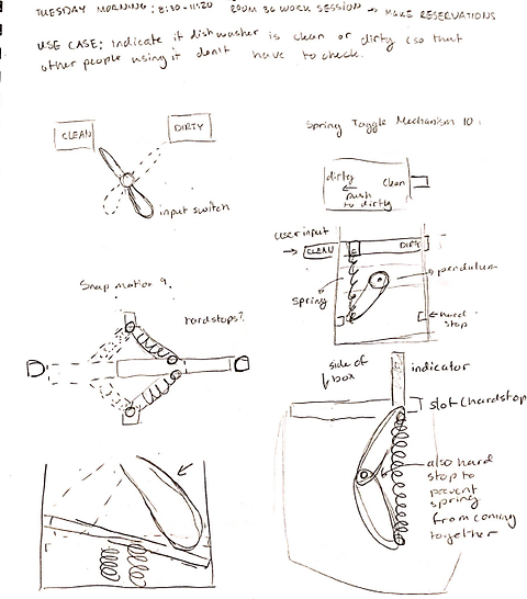
After spending the summer living at home, I became tired of never knowing if the dish washer hand been run or not. In fact, I got so fed up, that I made my own rudimentary indicator (pictured at left).
Our toggle indicator is intended to show whether the dishes currently in the dishwasher are clean or dirty, saving the user the need to inspect and guess at the current state of the dishes and whether they need to be emptied or washed. It is intended to be mounted on the wall just above the dishwasher, easily visible and accessible, but not infringing on useful counter space. We wanted to create a device with a pleasing appearance that matches a clean modern aesthetic.
INITIAL SKETCHES
Working with inspiration from initial research, including YouTube animations, we iterated through possible designs, focusing on making the mechanism simple, functional, and easy to use. Because we wanted the device to serve as an indicator for whether the dishwasher was clean or dirty we knew we would need to incorporate some kind of label, so we worked to include this from the beginning.


INITIAL DIGITAL PROTOTYPE
We began with a digital prototype so that we could easily laser cut pieces and quickly test our ideas. We created the initial prototype so that it would have a lot of flexibility and give us a range of configurations to test, while establishing the functionality of the main mechanism. We created 3 sides of a box, to give our prototype enough structural integrity to incorporate a spring. The two parallel sides had a hole for a dowel, which would act as a switch and various slots for a crossbeam that had a piece we termed the “pendulum” attached to it. In our physical prototype, we would attach the spring to a fixed point on the dowel and to the end of the pendulum.
INITIAL PHYSICAL PROTOTYPE
The initial digital prototype allowed us to make rapid changes to our prototype, as we were able to move our crossbeam both vertically and horizontally to change the initial and max load on the spring. We tested a different springs. The first spring had too great of a maximum extension and the displacement of shifting the dowel left and right was not enough to cause the pendulum to move. We tried moving the cross beam farther down the box, but realized this would increase the size of our mechanism significantly, placed additional stress on the pendulum, and still did not achieve the desired functionality. Instead of continuing to adjust the crossbeam we changed to a spring with a smaller extension. With this spring, we found that higher up and closer to the back of the box was the best position for the cross beam.
We had to experiment a little bit to find a good method for attaching the spring to the dowel. Initially we connected it using a binder clip, but this proved to easily come off or slip along the dowel. We solved this problem by tightening a zip tie on either side of the spring, however we knew this would be a temporary solution that we would have to update for our final version.
We also learned that we would need a larger screw to attach the pendulum to the spring and prevent it from slipping off. For this iteration we replaced the screw with a brass pin. We noticed that the pendulum was pulled up at the end because of the looseness of this pin at the required looseness of the screw in the top of the pendulum to allow it to pivot. We considered the possibility of adding a track to keep the end down but decided to wait until we had a more secure prototype and see if it was still necessary, since it would add friction and complexity.
Since the mechanism was successful, we decided to prototype the indicator portion of our device. We were able to use this indicator to make a rough mock up of the front face of our device, including the track for the indicator to travel through.


DIGITAL PROTOTYPE REVISIONS
With these results in mind, we went back to our SolidWorks assembly and made some changes:
Our revised prototype was functional, but much like the wooden pendulum, we realized the 3D pendulum printed on the Ultimaker would quickly show wear. In fact, the indicator portion broke off because it was too thin and did not print correctly. To address this we created a pendulum that was more sturdy and aesthetically pleasing by thickening the indicator and printing it on the Form 2 printer (a resin printer as opposed to a PLA printer) for our next iteration. We made the whole pendulum thicker, including the indicator and also filleted the edges of the part to help give it more structural integrity. Additionally, we changed the fastener to a shoulder screw for smoother rotation at the pivot.
-
Created a “front” piece with a slot for the end of the indicator to slide through that we could laser cut
-
Got rid of the other slots that did not best serve our bistable mechanism’s functionality
-
Decided to 3D print our pendulum, so that we could integrate the indicator into the pendulum shape instead of having to assemble them together
SECOND ROUND OF REVISIONS
In addition to changing the pendulum/indicator piece we also made updates to the box, adding a top and bottom face, experimenting with materials, and etching the words "clean" and "dirty" on the front face of the box. We also found rubber bumpers to add to the sides where the pendulum impacts for a more pleasing sound and less wear.


THIRD ITERATION AND FINAL ADJUSTEMENTS
-
Moved the dowel hole up, since the shoulder screw head has greater depth than the regular screw, making it collide with the spring in the current configuration.
-
Made the words CLEAN and DIRTY larger and added engraving around the edge so that when rastered into the acrylic it is visible
-
Added holes for mounting using command hooks
What we thought would be our last tweaks ended up being the first of a series of additional changes we made to reach the final model. Considering that we needed for the bistable mechanism to be operable with one hand, we had to mount it without adhesive which proved to be a greater challenge than we anticipated.
Mounting: When we tried introducing the command hooks to mount the indicator on the wall it introduced repeated complications. In order to insert the command hooks (so they were not blocked by the back piece) the holes had to be quite close to the edge. However, when we attached the double set of hooks, we realized that because of the design of the hooks, they were at an angle. Because they weren't level they did not fully adhere to the wall surface and came off when the device was used. We considered modifying the hooks to make them level, but after a couple different attempts we ultimately decided to change our approach. We changed the spring to reduce the force required to operate the switch and added rubber feet to the bottom to help resist movement during operation. We weren't as satisfied with this solution because it would mean the device would have to be on the counter and not have a fixed position. This would make it more obtrusive and make it more likely to be exposed to water, soap, etc. We decided to give the command hooks one more try and with the reduced force required for the new spring and a new configuration of the hooks it worked, so we went back to our plan of mounting the device on the wall.
Spring to Dowel Attachment: We finally solved the problem of attaching the spring to the dowel by screwing it in. We cut the dowel to the right size on the band saw. Then we filed it flat in the middle and drilled a hole on the drill press, and sanded it smooth.


REFLECTIONS
Through this project I gained a lot more confidence using the laser cutter and 3D printers and experimenting with different fasteners, such as shoulder screws, and other mechanical components (springs, bumpers, etc.). I also saw how having a specific use case could be helpful in guiding decisions and priorities while working on a project.
Lessons I took away from this project:
I want to thank the teaching team and all the PRL CAs for their help and advice; my coaching group for their feedback and support; and Kyla Windley, my partner, for her dedication and enthusiasm on this project.
-
Working as part of a group is rewarding, both through helping generate novel ideas, sharing knowledge, and maintaining motivation
-
A detailed and well thought out user story are helpful in decision making
-
Get feedback from people not directly involved in a project, especially with regard to how intuitive a design is
-
Persevering with adjustments to a design to make it fit the desired function and form is worth it